|
|
Electronics -- Atmel/AVR-programming: AVR Circuit
AVR RISC Programmer: (Quick) Electronic Circuit
This is really a trivial (quick solution) circuit as it applies
only half a dozen
parts (two resistors, one CMOS chip, a socket, a switch, some cable;
see further down for a more advanced
solution).
When building it, just be careful to not mix up the signal lines and
connect them correctly (which is not hard as most of them are grouped
in blocks where they lie next to each other in the correct order).
I provide two designs here which were tested and verified to work (but
come with absolutely no warranty for principal reasons).
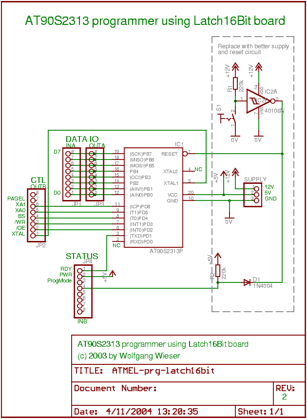
The first design allows to program the AT90S2313 device which is one of the
smallest AVR RICSs (2kb flash) and does not have a PAGEL (page load) pin.
The second one is for the ATMega161, a pretty large (40-pin, 16kb flash)
controller which has a PAGEL pin.
Building similar designs for other Microcontrollers is really easy:
just copy one of these (use the AT90S2313 if it has no PAGEL and the ATMega161
design it it does have a PAGEL pin) and verify the correctness of the
pins by looking at the "Memory Programming" section in the controller's
full data sheet (which can be obtained at
www.atmel.com).
Download the electronic circuit sheets:
| Device | Medium-quality 630x859 PNG image | High-quality colored PDF |
| AT90S2313 | ATMEL-prg-latch16bit.png (20kb) | ATMEL-prg-latch16bit.pdf (99kb) |
| ATMega161 | ATMEGA-prg-latch16bit.png (23kb) | ATMEGA-prg-latch16bit.pdf (100kb) |
Permission to copy and use these sheets is hereby granted provided credit is given where it is due.
AVR RISC Programmer: (Advanced) Electronic Circuit
The quick and easy-to-build circuit presented on this page worked for me but it clearly has its drawbacks: The button switch may bounce and there is no way to switch into running mode. Hence, I now recommend to use a more advanced supply circuit which replaces in the below (quick) ciruit all those parts on the right handside of the microcontroller (i.e. IC2(A), R1,2, D1, S1, SUPPLY).
The Technical Details
I will discuss the ATMega161 sheet here:
![ATMega161 programming board electronic circuit sheet [23kb]](ATMEGA-prg-latch16bit.png)
The large part in the center is the actual ATMega161 AVR RISC controller
which is best put on a 40 pin precision socket (or some quick
change socket).
The data IO lines during parallel programming
(PB0..PB7 here) are simply
connected to the channel A of the Latch16Bit
board. We need channel A input and output both connected because the
data flow is bidirectional.
In contrast, the channel B of the Latch16Bit board is used to connect the
the control and handshake lines. As for the input, only ready/busy from
the microcontroller is needed (PD1 here).
Furthermore, bit 2 is connected to +5V
(allow software detection of power) and bit 4 is used to detect
whether the device is in programming mode or not.
The CD40106 Schmitt trigger needs some explanation. The Atmel AVR RICSs are put into programming mode by applying +12V to the RESET line (while still using 5V supply voltage), so you need 5V and 12V supply voltages for the device. If you close the switch, the Schmitt trigger (you can use an inverter or a CD4011 as well) goes HIGH, i.e. to +12V (look at the supply pins; this is the reason why you need the plain 4xxx series CMOS chips which can be used with up to 15 (or 18) Volts and no HC, HCT or AC variants). To sum up: The microcontroller is in programming mode as long as the switch is closed.
The diode D1 and the resistor R2 are used to keep the 12V level off the Latch16Bit board's channel B input (because that would destroy the 74HC573 latch on that board).
| [home] [site map] [Impressum] [Datenschutz/privacy policy] |
|
|