|
|
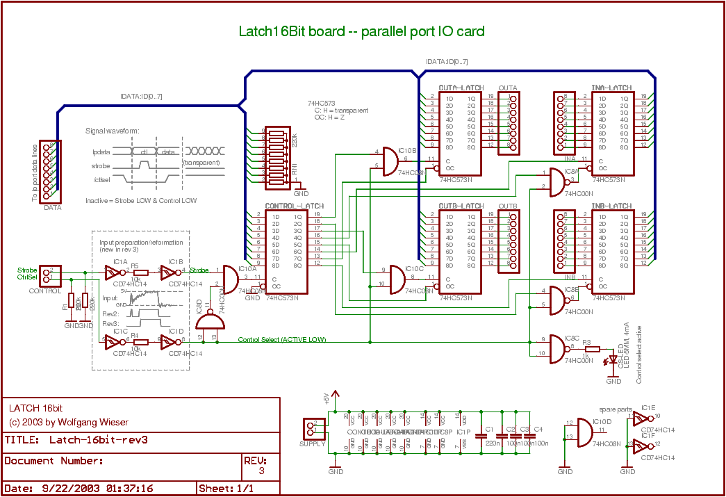
Latch16Bit Board: Circuit Sheet (Rev3)
This is the third revision of the design; in contrast to the second revision, it has an extra signal input preparation circuit for the two control signals. You are normally well-off with the rev2 but I needed to use this one due to poor signal quality. For more info, please check the rev2 page.
Download Latch16Bit board (rev3) electronic circuit sheet:
Medium-quality 1045x735 colored PNG image:
Latch16bit-rev3.png (30kb)
High-quality colored PDF:
Latch16bit-rev3.pdf (198kb)
Permission to copy and use this sheet is hereby granted provided credit is
given where it is due.
![Latch16Bit board (rev3) electronic circuit sheet [29kb]](Latch16bit-rev3-gray.png)
Little circuit description
Apart from the input preparation circuit, this design is identical to the rev2 circuit.
Two Schmitt triggers are used for the signal input preparation on the control lines. One Schmitt trigger would be enough to protect the board against long raise/fall times but if there is a very short peak at the beginning of the signal raise (as in my case), something additional is needed: The resistor (10k) between the two Schmitt trigger inverters together with the HC14 input capacity builds up an "RC delay". You may need to adjust the resistor yourself; for a 25ns peak, 10k turned out to be the value of choice.
| [home] [site map] [Impressum] [Datenschutz/privacy policy] |
|
|